CHAPTER 14 - MEASUREMENTS IN PRESSURE CONDUITS
3. Differential Head Flowmeters
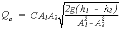
This class of flowmeters includes venturi, nozzle, and orifice meters. When properly installed and used, these meters have a potential accuracy of "1 percent. These meters have no moving parts but use the principle of accelerating flow by some form of constriction. Heads are measured upstream where the meter is the size of the approach pipe and downstream where the area is reduced to a minimum. The basic energy balance relationship is written as discussed in chapter 2. The velocity at one of these locations is solved for in terms of the difference of head between the two locations. Using the product of the upstream velocity and area results in discharge expressed as:
where:
Qa = discharge
A1 = upstream approach area
A2 = area of the throat or orifice opening
h1 = upstream head measurement
h2 = downstream head
g = gravity constant
C = coefficient determined experimentally
The term, h1 - h2, often written
in shorter form as ![]() h, is
the differential head that gives the name to this class of meters.
h, is
the differential head that gives the name to this class of meters.
The values of the effective discharge coefficient in both of the equation forms, for the same differential flowmeter, are the same. The coefficients are the same because the area divided by the square root of the denominator in each equation has the same value.
Equation 14-1 is valid for the venturi, nozzle, and orifice meters using proper respective effective coefficients. Each kind of flow meter has a different value of effective discharge coefficient. More details concerning what is accounted for by the effective discharge coefficient are covered in chapter 2.
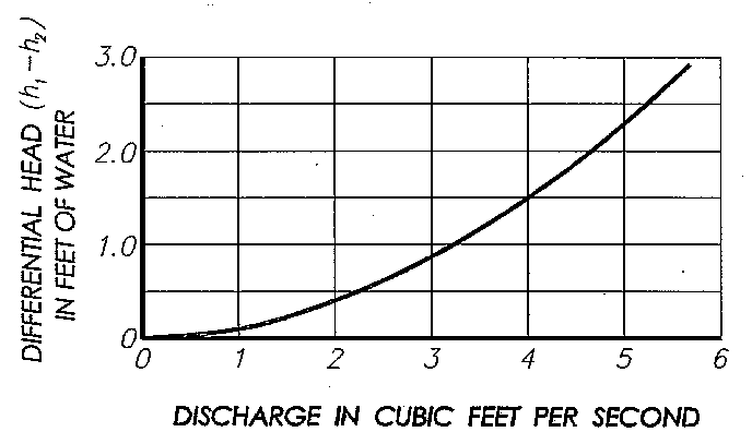
With differential flowmeters, the pressure difference between the inlet tap and the throat or minimum pressure tap is related to discharge in tables or curves using the suitable coefficients with the proper equation. An example discharge curve is shown for an 8-inch (in) venturi meter on figure 14-1. Thus, the meters may serve as reliable flow measuring devices.
|
|
(a) Venturi Meters
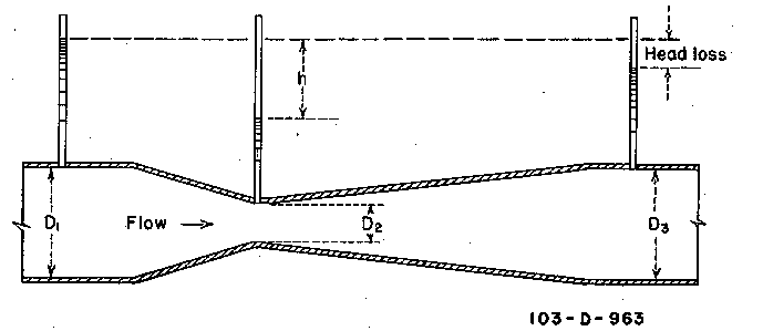
Venturi meters (figure 14-2) are one of the most accurate type of flow measuring device that can be used in a water supply system. They contain no moving parts, require very little maintenance, and cause very little head loss. Tables or diagrams of the head difference versus rate of flow may be prepared, and flow indicators or flow recorders may be used to display the differential or rate of flow. Venturi meters are often used in the laboratory to calibrate other closed conduit flow measuring devices.
|
|
The American Society of Mechanical Engineers (1983) and International Organization for Standardization (1991) contain details of pipeline meter theory, equations, coefficients, and tables with application instructions.
The effective discharge coefficient for venturi meters ranges from 0.9 to about unity (Streeter, 1951; American Society of Mechanical Engineers, 1983) with turbulent flow, and it varies with diameter ratio of throat to pipe.
The smaller commercial venturi meters are made of brass or bronze and are available for pipe sizes up to about 2 inches (in) diameter. Larger meters are usually made of cast iron with inner bronze linings. Some larger venturi meters have been constructed of concrete with the convergence and the throat made of finished metal. Large venturi meters have not been standardized for general irrigation practice, and the sizes, shapes, and coefficients are not well known. Accuracy and performance should be specified by purchase contract for large venturi meters. Some relatively simple and effective venturi meters have been made from precast concrete (Summers, 1952; 1953) and plastic (Replogle and Wahlin, 1994) pipe sections and fittings.
In the past, the expense of venturi meters and the fact that they must always operate with full pipelines have restricted their use on a broad scale in irrigation systems. The increasing demand for accurate flow measurements in pressure conduits will likely result in greater use of venturi meters in the future. Because venturi meters have smoothly varying flow boundaries, they have been used for measuring sewage and flow carrying other materials. Sometimes, this usage may require clean water backflushing for clearing manometer tubing. With trash-carrying flow that would require frequent flushing, small continuous purging flows have been used to keep material from plugging or entering the pressure taps between and during pressure head measurements. Many variations of the meter exist, each of which is tailored to meet the requirements of specific types of installations.
(b) Nozzle Meters
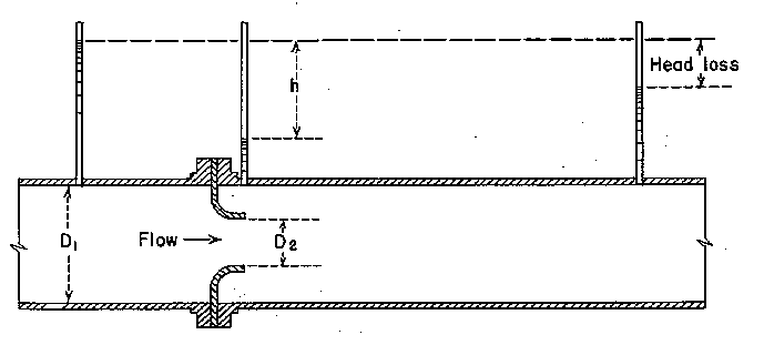
In effect, the flow nozzle is a venturi meter that has been simplified and shortened by eliminating the gradual downstream expansion (figure 14-3). The streamlined entrance of the nozzle causes a straight jet without contraction, so its effective discharge coefficient is nearly the same as the venturi meter. Flow nozzles allow the jet to expand of its own accord. This feature causes a greater amount of turbulent expansion head loss than the loss that occurs in venturi meters, which suppress exit turbulence with a gradually expanding tube boundary.
|
|
The effective coefficient of discharge for flow nozzles in pipelines varies from 0.96 to 1.2 for turbulent flow and increases as the throat-to-pipe-diameter ratio increases.
Frequently, the upstream pressure connection is made through a hole in the wall of the conduit at a distance of about one pipe diameter upstream from the starting point of the flare of the nozzle (ASME, 1983). Thus, the pressure is measured before it curves to enter the nozzle. The downstream pressure connection may be made through the pipe wall just above the end of the nozzle tube (ASME, 1983).
Flow nozzles have been made from precast concrete pipe and used in the field. Flow nozzles have not been used extensively for measuring irrigation water, probably because this application lacks standardization. Discharge tables provided by a manufacturer agreed closely with independent calibration tests and studies (Summers, 1952).
(c) Orifice Meter
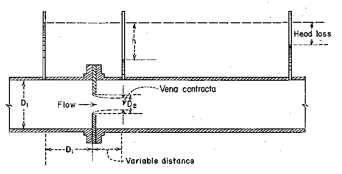
The most common differential-pressure type flowmeter used in pipelines is the sharp-edged orifice plate (figure 14-4). These meters are frequently used in irrigation applications for measuring well discharges and agricultural chemicals that are injected into irrigation flows. The latter are usually small with details of installation and operation furnished by the manufacturers. Therefore, only larger diameter orifice plates in round pipes will be discussed here. Personal computers and the generalization of discharge coefficients renewed interest in the orifice as a primary device (Furness, 1987).
|
|
Applications with proper water quality, careful attention to installation detail, and proper operation techniques (Hobbs, 1987) make these flowmeters capable of producing accuracy to within 1 percent. However, the usual maintenance and pipe conditions that generally occur in irrigation pipe systems limit field accuracies to within 3 to 5 percent of actual.
Advantages of the orifice plate are its simplicity and the ability to select a proper calibration on the basis of the measurements of the geometry (Dijstelbergen, 1982). Disadvantages of the orifice plate include the long, straight pipe length requirements and the limited practical discharge range ratio of about one to three for a single orifice hole size. However, the location of the range can be shifted by using sets of plates for changing orifice hole sizes. This shift, in effect, provides a range ratio increase. Calibrations based on tap locations relative to pipe diameter, rather than orifice diameter, make this feasible because the same tap locations can be used for different orifice plate hole sizes.
(1) The Flow Rate Equation
The equation now commonly used to calculate the flow rate from the pressure differential and other relevant parameters is:
![]()
![]()
where:
Q = the discharge
Cd = the product CCv
C = a coefficient determined experimentally
Cv = the velocity of approach factor
A = the area of the orifice hole
g = the acceleration of gravity
![]() h = the differential head
h = the differential head
If differential pressure sensing equipment is used as the secondary
measuring devices, then 2g![]() h
must be replaced with 2
h
must be replaced with 2![]() P/D,
where
P/D,
where ![]() P is differential
pressure and D is the density of the flowing water.
P is differential
pressure and D is the density of the flowing water.
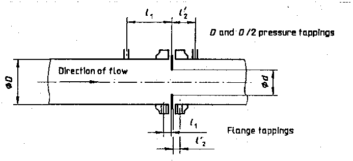
(2) Standardization of Tap Locations
Originally, the so-called vena-contracta tap (minimum contracted orifice jet diameter) was standardized. For those, the location of the downstream tap depended on the orifice hole size in the orifice plate. This diminished the possibility of altering the range by changing orifice plates because the tappings would also have to be relocated for each new plate size.
More recent orifice standards are based on extensive experimental data and can be applied with a fair degree of confidence. Studies carried out in Germany, the United States, France, and Britain resulted in the present ISO-5167 (1991) (adapted from British Standards-1042 [1943], and Dijstelbergen [1982]). The standards list the geometry of the devices, the installation conditions to be observed, and the equation relating flow and pressure differential. Three types (figure 14-5) of differential measuring taps as internationally standardized are:
|
|
(3) Orifice Plate and Hole Requirements
Orifice plates require careful installation. The orifice plate coefficient is generally affected more by misalinement and disturbed velocity distributions than other differential-pressure meters because the abrupt pressure changes take place near the plate. Poor installation of an otherwise properly designed orifice plate can cause as much as a 20-percent error (Humphreys, 1987). The orifice plate should be mounted in such a way that it is possible to inspect at least the orifice plate and preferably the adjacent piping.
The orifice hole diameter should be at least 0.5 in, and its upstream edge should be free of visible dents, burrs, and rounding. The orifice hole must be bored perpendicular to the plate. The bore hole cylinder length must be between 0.005 and 0.02 times the pipe diameter (D). If the plate is thicker than 0.02D, the downstream orifice must be beveled at an angle between 30 to 60 degrees from horizontal. Centering of the plate orifice hole, as specified in the standard, is particularly difficult to meet for small pipes.
The plate shall be mounted perpendicular to the pipe axis. The orifice plate material should be thick enough so it will not bow under the differential pressure. The plate faces shall be flat and parallel. The plate thickness shall be less than 0.05 times the pipe diameter, and its upstream face shall be have a quality finish.
(4) Meter Approach and Exit Requirements
Downstream from pipe fittings, the required length of straight pipe
approaching orifice meters varies with type, number, and orientation of
fittings and increases in proportion to ![]() (ratio
of orifice to pipe diameter). For example, a single 90degree bend
requires from 6 to 18 di-ameters of straight approach pipe ahead of the
upstream pressure tap for
(ratio
of orifice to pipe diameter). For example, a single 90degree bend
requires from 6 to 18 di-ameters of straight approach pipe ahead of the
upstream pressure tap for ![]() increasing
from 0.2 to 0.75 (ISO, 1991). Two 90-degree bends in the same plane require
7 to 21 diameters for the same
increasing
from 0.2 to 0.75 (ISO, 1991). Two 90-degree bends in the same plane require
7 to 21 diameters for the same ![]() range. Two or more bends in different planes require 17 to 35 di-ameters.
Globe valves require 9 to 18 diameters for
range. Two or more bends in different planes require 17 to 35 di-ameters.
Globe valves require 9 to 18 diameters for ![]() increasing
from 0.2 to 0.75. Gate valves require 6 to 15 approach diameters. An expander
fitting requires 8 to 19 diameters. A reducer fitting requires 5 to 15 diameters
of straight pipe upstream for
increasing
from 0.2 to 0.75. Gate valves require 6 to 15 approach diameters. An expander
fitting requires 8 to 19 diameters. A reducer fitting requires 5 to 15 diameters
of straight pipe upstream for ![]() ranging
from 0.5 to 0.75, which differs from the previously mentioned values. Four
to eight diameters of straight pipe are required downstream from the pressure
taps.
ranging
from 0.5 to 0.75, which differs from the previously mentioned values. Four
to eight diameters of straight pipe are required downstream from the pressure
taps.
(5) Coefficient of Discharge
Accurate values for Cd have been developed for the
standard tap locations. If the orifice-plate geometry and its installation
conform to the orifice specifications of ISO 5167, a good estimate of performance
can be developed by applying the Stolz equation appearing in those standards.
This equation was developed by Stolz, who logically showed that the coefficients
of the different taps normalized by pipe diameter are related. Thus, the
value of the coefficient of discharge, Cd, depends on
the particular tapping arrangement, the Reynolds number (Re) (VD/![]() ),
and the diameter ratio,
),
and the diameter ratio, ![]() , as defined
in equation 143. Originally, the older coefficients were separately
determined for each tapping arrangement for specific orifice hole sizes.
, as defined
in equation 143. Originally, the older coefficients were separately
determined for each tapping arrangement for specific orifice hole sizes.
In large pipe diameters, for example, the coefficient of the corner taps and flange taps should not differ. For small area ratios, all coefficients for different taps should be equal. Stolz statistically fitted the available data resulting in the unified equation given in ISO 5167 covering all tapping arrangements. This equation for Cd is:
Cd = 0.5959 + 0.0312![]() 2.1
- 0.1840
2.1
- 0.1840![]() 8 + 0.0029
8 + 0.0029![]() 2.5(106/Re)0.75+
0.0900(L1/D)[
2.5(106/Re)0.75+
0.0900(L1/D)[![]() 4/(1
-
4/(1
- ![]() 4)]- 0.0337 (L2/D)
4)]- 0.0337 (L2/D)![]() 3
(14-3)
3
(14-3)
where:
Cd = coefficient of discharge
L1 = the tap distance from the upstream face of the plate
L2 = the tap distance from the downstream face of the
of the orifice plate
D = the pipeline diameter
![]() = the ratio of orifice diameter
to pipe diameter
= the ratio of orifice diameter
to pipe diameter
Re = the Reynolds number (VD/![]() )
)
V = the pipeline velocity
![]() = the kinematic viscosity of the
water
= the kinematic viscosity of the
water
The minimum allowable Reynolds number varies with diameter, tapping
arrangement, and ![]() . The Reynolds
number (VD/
. The Reynolds
number (VD/![]() ) for flange and
(D-D/2) taps must be greater than 1,260
) for flange and
(D-D/2) taps must be greater than 1,260![]() 2D.
For corner taps Reynolds number must be greater than 10,000 for
2D.
For corner taps Reynolds number must be greater than 10,000 for ![]() greater than 0.45. For
greater than 0.45. For ![]() less
than 0.45, the Reynolds number must be greater than 5,000.
less
than 0.45, the Reynolds number must be greater than 5,000.
The first three terms of equation 14-3 give the corner tap coefficient when Reynolds number (Re) effect is insignificant. The fourth term introduces Reynolds number effect. The last term accounts for the distance of flange and D-D/2 taps from the upstream face of the orifice plate. Although the equation appears to give a coefficient value for all tapping locations, standardized or not, it was not developed with data for other than standard locations and, therefore, is not recommended for nonstandard tapping locations. The coefficients by this equation are substantially the same as found in older presentations. Differences come mainly from the data fitting method. Uncertainty of the coefficient is claimed to be less than "1 percent, exceeding the usual requirements for irrigation use.
The equation which relates flow rate to head differential and other parameters may seem to be rather complicated but is a minor inconvenience with modern computer capabilities. For the usual irrigation practice that accepts meter accuracies within "3 percent or more, the above precautions can be relaxed considerably.