|
|
CHAPTER 10 - CURRENT METERS
19. Computations of Discharges
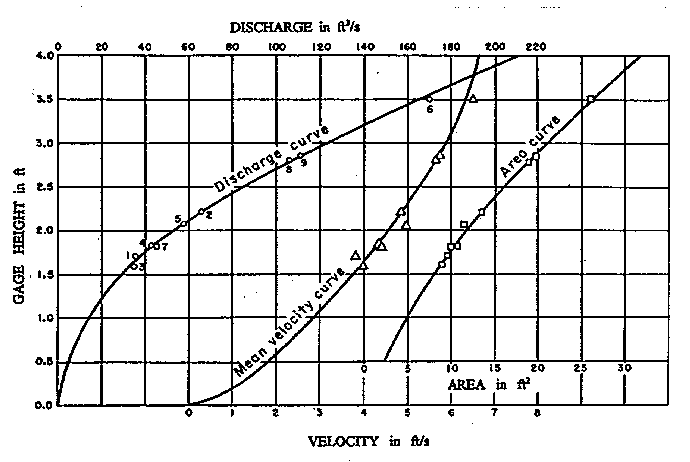
Current-meter measurements made at several specific flows can be used to obtain discharge, velocity, and area curves that apply to all inclusive gage heights by plotting the appropriate data on cross-section or graph paper (figure 10-18). Discharges, corresponding mean cross-sectional velocities, and cross-sectional areas are plotted on the horizontal axis. Corresponding gage heights are plotted on the vertical axis. Three separate curves are drawn through these data points.
|
|
The probable area curve is established first by drawing the most probable line through the data points. Using this curve, the accuracy of the area computations and of the flow depth measurements may be checked. Next, the computed mean cross-sectional velocities are plotted, and a curve is drawn through the points. This curve provides a check on the velocity computations and helps detect changes in velocity that may occur in the canal because of changing roughness or silting in the canal.
Finally, the discharge curve is drawn through the computed discharge points. If flow conditions in the channel did not change resistance significantly during the period needed for measurements over the full range of canal flows, the curve will generally be easy to draw. If the relationship of discharge to gage height was affected by growths or sediment deposits, one or more additional discharge curves must be drawn. The number of rating curves required for a cross-section location depends upon the degree of the flow restric- tions encountered and the rate at which the restrictions developed. These curves will generally be parallel to, but slightly displaced from, the curve for the clean canal. For the periods when the change is in progress, discharges may be estimated by proportioning between curves for the clean and restricted conditions on a time basis.