|
|
CHAPTER 8 - FLUMES
Although Parshall flumes are in extensive use in many western irrigation projects, they are no longer generally recommended because of the advantages of long-throated flumes previously cited and the disadvantages of Parshall flumes to be subsequently discussed. Some states specify the use of Parshall flumes by law for certain situations.
In the past, it was common to size and set flumes for 95-percent submergence to reduce approach flow depths 4 to 6 in. The 1976 second edition of this manual gives detailed examples of selecting size and setting crest elevation for free flow and intended submergence. Although correction methods for determining submerged discharge exist, designing flumes for submerged flow measurement is no longer considered good design practice because it compromises accuracy. For example, imprecision of head measure-ment increases discharge error by 4 to 20 percent over the primary free-flow accuracy of 3 to 5 percent. In addition, a recent study (Peck, 1988) found a 12-percent discontinuity in the submergence correction function for a 1-ft flume depending upon whether downstream measuring head results from a falling or rising water surface.
Designing and setting Parshall flumes for submerged flow measurement is not usually recommended because less expensive, long-throated flumes can be designed that approach or exceed 90 percent submergence limits with a single upstream head measurement. Moreover, the absolute required drop in water surface is usually less for the long-throated flumes, particularly the modified broad-crested weir styles.
Because so many Parshall flumes are currently in use, the remaining part of this section is concerned mainly with structural dimensions for checking existing flumes, equations for computing discharges, free-flow discharge tables for each size flume, plots for submerged discharge measurement corrections, and head loss curves for assessing upstream depth changes caused by downstream delivery depth changes.
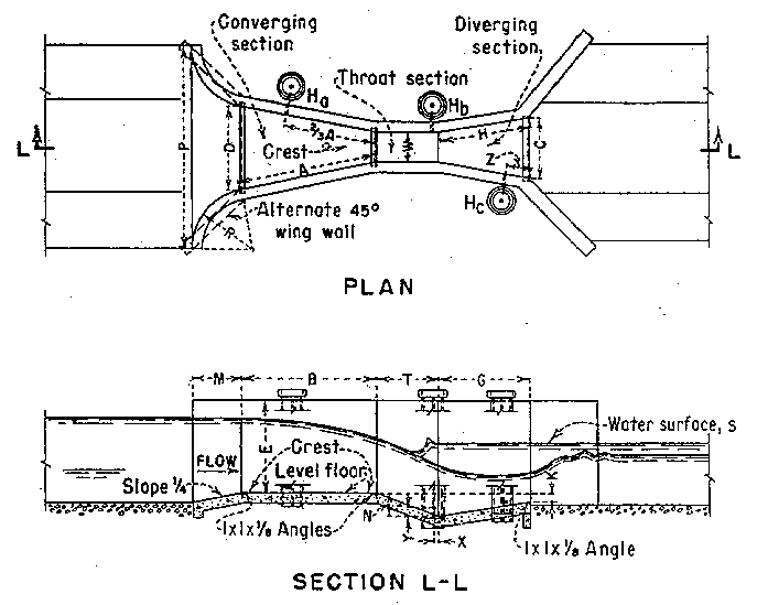
Care must be taken to construct Parshall flumes according to the structural dimensions given on figure 8-9. This factor becomes more important as size gets smaller. The portion of the flume downstream from the end of the converging section need not be constructed if the flume has been set for free flow where it is not expected to operate above submergence limit. This truncated version of the Parshall flume is sometimes referred to as the Montana flume. Submergence corrections or discharge cannot be determined for Montana flumes or other modified Parshall flumes because they do not include the part of the full Parshall flume where the submergence head, hb, was measured during calibration.Different size Parshall flumes are not geometrically proportional. For example, a dimension in the 12-ft flume cannot be assumed to be three times the corresponding dimension in the 4-ft flume. Each of the flumes on figure 8-9 is a standard device and has been calibrated for the range of discharges shown in the table. The flumes can reliably measure free-flow discharge to within "3 to "5 percent, plus head detection error, if standard dimensions are attained during construction, the flume is correctly set, and the flume is operated and maintained according to the recommended procedures.
|
|
|
|
Parshall flume sizes are designated by the throat width, W, and dimensions are available for flumes from the 1-in size for free flow of 0.03 ft3/s at 0.2 ft of measuring head up to the 50-ft size with 3,000 ft3/s at a head of 5.7 ft. The free-flow discharge range and dimensions for Parshall flumes are given on figure 8-9. The minimum flows in this table up to the 1-ft-size flume are for a head of 0.2 ft because measuring at smaller heads results in imprecision of head measurement and surface tension effects. The remaining discharge limits are based on the range of the calibration data and practical size considerations.
(a) Free-Flow Discharge Tables and Equations
Parshall flumes were calibrated empirically to generate the free-flow head versus discharge rating for the 1-in to 50-ft flumes. Some of the larger sizes were not directly calibrated but were scale modeled. The free-flow discharge equations for the standard Parshall flume sizes are of the form:
![]() (8-3)
(8-3)
where:
ha = measuring head (ft)
Q = discharge (ft3/s)
C and n for each size are given in table 8-6
Head versus discharge is given in tables A8-7 through A8-21 for all sizes (see appendix).
Table 8-6
Coefficients (C) and exponents (n) for Parshall flumes for equation 8-3
|
Throat width |
Coefficient (C) |
Exponent (n) |
|
1 in |
0.338 |
1.55 |
|
2 in |
0.676 |
1.55 |
|
3 in |
0.992 |
1.55 |
|
6 in |
2.06 |
1.58 |
|
9 in |
3.07 |
1.53 |
|
1 ft |
3.95 |
1.55 |
|
2 ft |
8.00 |
1.55 |
|
3 ft |
12.00 |
1.57 |
|
4 ft |
16.00 |
1.58 |
|
5 ft |
20.00 |
1.59 |
|
6 ft |
24.00 |
1.59 |
|
7 ft |
28.00 |
1.60 |
|
8 ft |
32.00 |
1.61 |
|
10 ft |
39.38 |
1.60 |
|
12 ft |
46.75 |
1.60 |
|
15 ft |
57.81 |
1.60 |
|
20 ft |
76.25 |
1.60 |
|
25 ft |
94.69 |
1.60 |
|
30 ft |
113.13 |
1.60 |
|
40 ft |
150.00 |
1.60 |
|
50 ft |
186.88 |
1.60 |
(b) Submerged Flow Determination
Calibration tests show that the discharge at a given upstream measuring head is not reduced until the submergence ratio, hb/ha (submergence head to measuring head) expressed in percent, exceeds the following values:
50 percent for flumes 1, 2, and 3 in wide
60 percent for flumes 6 and 9 in wide
70 percent for flumes 1 to 8 ft wide
80 percent for flumes 8 to 50 ft wide
These submergence limits are based on two measuring head locations shown in figure 8-9 within the structure and do not measure all the head loss caused by the flume. Thus, these limits do not represent the total required head loss needed to measure flow with one head measurement. The method of determining submerged flow discharge varies with different flume size groups. Examples are provided later.
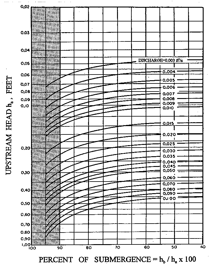
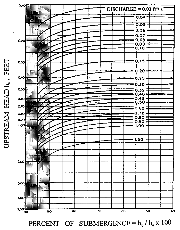
(1) Submerged Flow in 1- Through 3-Inch Flumes
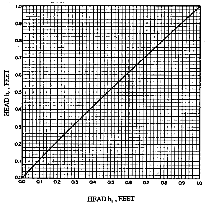
Submergence begins to reduce the discharge through the 1-, 2-, and 3-in flumes when it exceeds 50 percent. To determine discharges for submerged flows, the heads ha and hb are used with figures 8-10, 811, and 8-12. Users found they had difficulties in obtaining field readings of hb because of wave interference. To solve this problem, figure 8-13 was developed to relate hb to hc, which is located at the downstream end of the flume divergence where the water surface is smoother.
|
|
|
|
|
|
|
|
In a 3-in flume, assume ha of 0.20 ft and the downstream head measured at the hc gage is 0.19 ft. To determine the discharge, turn to the curve on figure 8-13, which shows the relationship of hc to hb. For a value of hc equal to 0.19, hb is found to be 0.17. The submergence, hb/ha = 0.17/0.20 = 0.85 or 85 percent.
Enter figure 8-12 with the value of the upstream head, ha, of 0.20 and move horizontally to the right to the vertical line for hb/ha of 85 percent. This intersection point lies about seven-tenths of the distance from the curved discharge line for 0.06 ft3/s, toward the 0.07ft3/s line. The interpolated discharge value is 0.067 ft3/s. This rate of flow for submerged conditions is considerably less than the free-flow discharge value of 0.082 ft3/s for ha of 0.20 ft. As mentioned previously in section 7 of this chapter, correcting for submergences greater than 90 percent does not provide reliable accuracy.
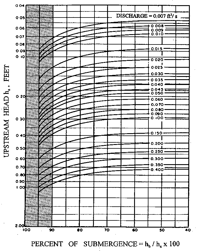
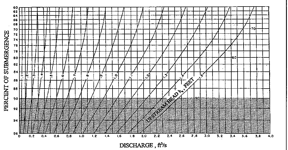
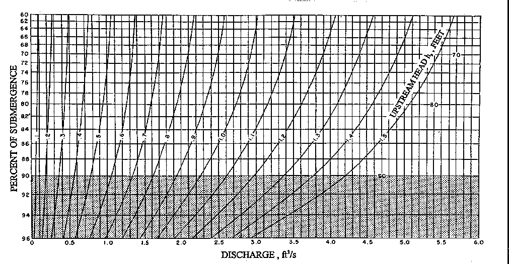
(2) Submerged Flow Determination With 6- and 9-Inch Flumes
When 6- and 9-in flumes are operating with submergences greater than 60 percent, the discharge is directly determined using figures 8-14 and 8-15, respectively. For example, determine the discharge through a 6-in flume when ha is 1.32 ft and hb is 1.20 ft. The submergence ratio, 1.20 divided by 1.32, is 0.91, or 91 percent. On figure 8-14, find 91 percent along the left-hand vertical scale and follow the 91-percent line horizontally to intersect the curved line for ha, which is 1.32 (one-fifth the distance between the 1.3 and 1.4 lines). Then move vertically downward from this point to the scale at the base of the diagram and find that the submerged rate of flow is 2.02 ft3/s. As mentioned previously in section 7 of this chapter, correcting for submergences greater than 90 percent does not provide reliable accuracy.
|
|
|
|
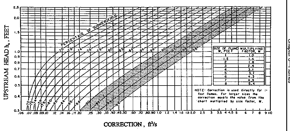
(3) Submergence Correction for 1- to 8-Foot Flumes
The submergence corrections that must be subtracted from the free-flow values in table A8-12 to obtain submerged flow values in a 1-ft flume are shown on figure 8-16. For example, in a 1-ft flume with ha of 1.00 ft, the discharge from table A8-12 is 4.00 ft3/s. If hb is measured to be 0.8, the submergence, hb/ha, is equal to 80 percent. If figure 812 for ha is 1.00 and submergence is 80 percent, the correction is 0.35 ft3/s. Therefore, submergence would result in a reduction in discharge of 0.35 ft3/s or an actual discharge of 3.65 ft3/s, compared to a free-flow discharge of 4.00 ft3/s.
|
|
Submergence correction values for 1- to 8-ft flumes are obtained from figure 8-16, but the procedures contained in the note in the figure must be followed. These procedures state that values read from the curve are multiplied by the M values listed in the table on figure 8-16 for each size to obtain the product or correction to subtract from the free discharge values.
For example, assume that submerged flow occurs in a 3-ft flume where ha is 2.10 ft and hb is 1.89 ft. The submergence ratio, 1.89 divided by 2.10, is 0.90, or 90-percent submergence. The free-flow discharge for a 3-ft flume with ha of 2.10 is found from table A8-12 to be 38.4 ft3/s. On figure 8-16, ha is 2.10 and submergence is 90 percent: a correction of 3.5 ft3/s. However, this correction is only for a 1-ft flume. For a 3-ft flume, the correction must be multiplied by 2.4 (from tabulation on figure 8-16) to get the total correction of 8.4 ft3/s. The corrected submerged discharge is, therefore, 38.4 minus 8.4, or 30.0 ft3/s. As mentioned previously in section 7 of this chapter, correcting for submergences greater than 90 percent does not provide reliable accuracy.
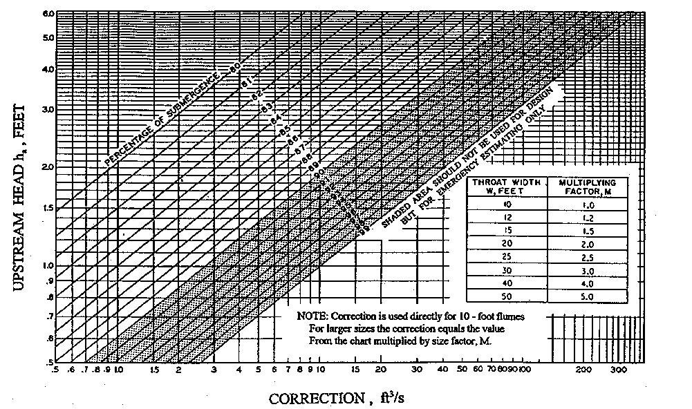
(4) Submergence Correction for 10- to 50-Foot Flumes
The submergence ratio, hb/ha, expressed in percent, and the ha value are used on figure 8-17 to obtain the correction to be subtracted from the free-flow discharge determined from tables A8-12 through A8-20.
|
|
The correction values, indicated along the base of the diagram on figure 817, give the number of cubic feet per second to be subtracted for each 10 ft of crest width, W. To aid in determining the multi plying factor, a tabulation has been incorporated on figure 8-17.
Thus, to determine the discharge for submerged flow through a 20ft flume when ha is 3.25 ft and hb is 3.06 ft, first determine the submergence ratio:

Enter at the left side of the diagram of figure 8-17, and at ha equals 3.25, project a horizontal line to intersect the 94-percent line, then continue on to one-tenth of the distance between the 94- and 95per-cent lines. Vertically below this point on the horizontal scale is the correction value, 56 ft3/s. For a 20-ft flume, the multiplying factor is 2.0 (from tabulation on figure 8-17), and the total correction is:
2.0 x 56 = 112 ft3/s
The free discharge value from table A8-16 for ha of 3.25 is about 503 ft3/s. Therefore, the submerged flow is 503 minus 112, or 391 ft3/s. As mentioned previously in section 7 of this chapter, correcting for submergences greater than 90 percent does not provide reliable accuracy.
(c) Head Loss Determination
Flumes are obstructions that produce backwater that extends upstream from the flume and raises the water surface in the approach channel. This difference in eleva-tion of the flow upstream from the structure with and without the flume in place is the head loss caused by the flume. The difference in measuring heads is not the head loss of Parshall flumes.
Downstream channel depth-discharge relationships often change with changes of downstream flow resistance, which frequently varies with sediment deposits, debris, canal checking operations, and aging. Downstream changes in flow resistance plus head loss can cause overtopping of upstream approach channel banks. Thus, irrigation system managers that have Parshall flumes need to determine head losses.
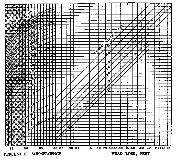
(1) Head Loss for 10- to 50-Foot Throats
The increase in depth upstream from the structure or the head loss for the 10- to 50-ft flume is determined using figure 8-18. For example, assume a 20-ft flume is set 1.4 ft above the bottom of the channel, is discharging 950 ft3/s, and is at 90-percent submergence. The head loss from figure 8-18 is obtained by following the vertical 90-percent submergence line up to the curved discharge line for 950 ft3/s, projecting a horizontal line to the sloping 20-ft throat line, and coming vertically down to the head loss scale reading of 0.9 ft.
|
|
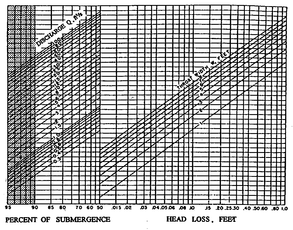
(2) Head Loss for 1- to 8-Foot Throats
The head loss values for flumes 1 to 8 ft wide can be determined from figure 8-19. For example, assume a 4-ft flume which has a 70-percent submergence with 20 ft3/s, and determine the head loss. Using figure 8-19, find the intersection of the vertical 70-percent line with the slanting 20-ft3/s discharge line in the left side of the figure. Then, from this intersection, project a horizontal line to the intersection with the slanting line for the 4-ft throat width in the right side of the figure. From this point, project vertically down to read head loss on the bottom scale, which reads 0.43 ft.
|
|
(3) Head Loss for 9-Inch Throats and Smaller
Losses for 9in flumes and smaller are usually less critical, and the elevation of the upstream water surface is determined in the manner used for the
1-, 2-, and 3-in flumes. The difference between ha and hb is considered an adequate estimate of head loss.